
Flex Circuit PCBs Improve Product Reliability
Depending on the application, flex circuit PCBs can save up to 60% of weight and space compared to rigid or wire harnesses. This allows for a smaller device and lighter end product without compromising on the reliability of the product. The flex circuit pcb also provides better shock, vibration, and drop test results due to its ductility.
A flexible circuit is a printed circuit board that uses one or more copper layers to connect components and conductors in a flexible manner. They can be manufactured using a variety of materials and can be laminated to both rigid and flexible substrates. Flex circuits are typically used for high-speed and high-frequency applications, as well as in dynamic environments where the circuit board is required to flex.
To ensure that a flex circuit board can handle the required bending and flexing, careful design considerations are needed for aspects like trace spacing, bend radius, adhesives, vias, tear propagation, shielding, and thermal stresses. These features will help ensure that the flex circuit will be able to withstand millions of bending cycles without breaking or losing connectivity.
When designing a flex circuit pcb, designers should make sure that the neutral bend axis is as close to the center of the flex circuit stack as possible. This will allow for more even distribution of the destructive forces that are generated during flexing. It is also a good idea to stagger the traces across each layer. Additionally, a coverlay can be added to the flex circuit to provide insulation and protection.
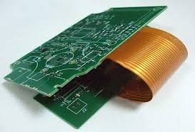
How Flex Circuit PCBs Improve Product Reliability
The copper foil that is etched to form the conductive paths on a flexible circuit is normally made of either electrodeposited or wrought copper. The choice of metal depends on a balance between cost, physical and electrical performance attributes, and material thickness tolerances. The etching process for a flexible circuit is usually done through a combination of dry film and wet chemical processing techniques.
In addition to the conductive paths, a dielectric coverlay is normally added to the flex circuit for insulation and protection. This can be made of a variety of materials, including polyimide and Kapton films. An epoxy or acrylic based adhesive is then used to bond the base substrate and the copper foil. Plated through holes (PTH) are then added to the flex circuit for interconnects.
Some flex circuits may require stiffeners which are thin, rigid parts that are laminated to the flex to add mechanical stability. These can be used in areas that are expected to experience more stress such as edge connectors or mounting holes. Other options include adding a shielding film to selected areas of the flex for electromagnetic interference (EMI) protection. This option is typically a little more expensive than just adding the extra stiffeners.
Flex circuit PCBs (Printed Circuit Boards) are revolutionizing aerospace applications by offering a range of advantages that traditional rigid PCBs cannot match. These flexible circuits are integral in modern aerospace systems due to their versatility, durability, and efficiency in high-performance environments.

+ There are no comments
Add yours